EMS Device Control
Technical Details quality EMS Device
Please watch the video with the English-speaking engineer carefully, as it explains all necessary details.
Important: This will help avoid unnecessary questions, as everything is clearly explained in the video.
This Google Drive folder contains images of PCBs, control inputs, and various technical components from multiple EMS devices by different manufacturers, along with additional design details and internal hardware references.
Watch our YouTube channel to learn more about the product.
Our vision is to create a world-class EMS product with Apple-level quality. With 15 years of market experience and a successful business, we’re focused on scaling, not experimenting. We’ve analyzed 5 existing EMS devices and their apps to reverse-engineer a superior version using the best components, as outlined in this documentation. We’re ready to begin with a working model and continuously improve with future updates and releases.

iBody User Manual
Discover how to use iBody safely and effectively.
The iBody User Manual covers everything you need to get started — from suit setup, app connection, and training modes to safety guidelines, care instructions, and progress tracking. Learn how to customize your sessions, avoid common risks, and achieve results with confidence.

Technical Details
Explore the advanced technology behind iBody.
Get a detailed overview of device specifications, including weight, dimensions, battery capacity, charging requirements, operating conditions, and stimulation parameters like pulse width, frequency, and intensity range.
Training Program Parameters
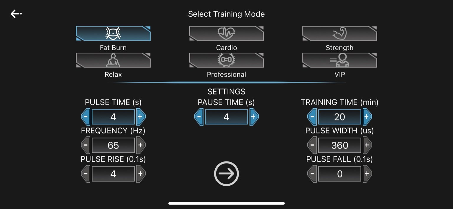
1. Fat Burn
-
Pulse Time: 4 seconds
-
Pause Time: 4 seconds
-
Frequency: 65 Hz
-
Pulse Width: 360 µs
-
Pulse Rise: 0.4 seconds (4 × 0.1s)
-
Pulse Fall: 0 seconds
-
Training Time: 20 minutes
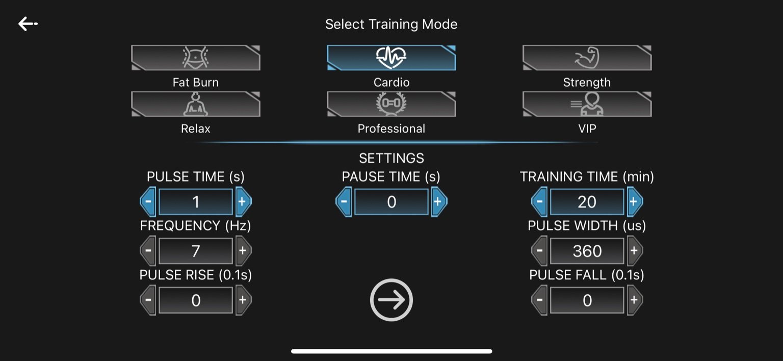
2. Cardio
-
Pulse Time: 1 second
-
Pause Time: 0 seconds
-
Frequency: 7 Hz
-
Pulse Width: 360 µs
-
Pulse Rise: 0 seconds
-
Pulse Fall: 0 seconds
-
Training Time: 20 minutes
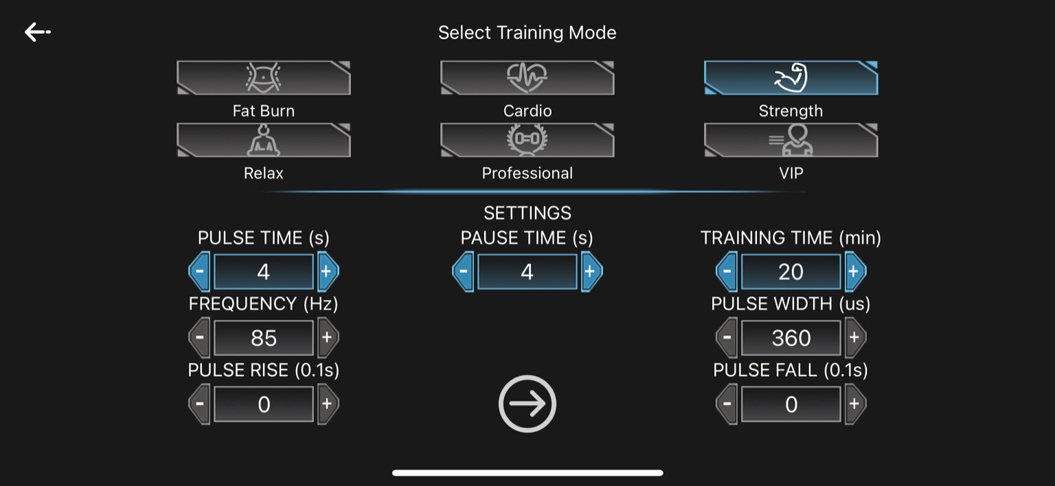
3. Strength
-
Pulse Time: 4 seconds
-
Pause Time: 4 seconds
-
Frequency: 85 Hz
-
Pulse Width: 360 µs
-
Pulse Rise: 0 seconds
-
Pulse Fall: 0 seconds
-
Training Time: 20 minutes
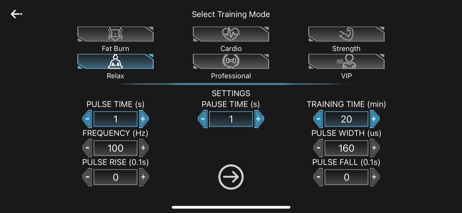
4. Relax
-
-
Pulse Time: 1 second
-
Pause Time: 1 second
-
Frequency: 100 Hz
-
Pulse Width: 160 µs
-
Pulse Rise: 0 seconds
-
Pulse Fall: 0 seconds
-
Training Time: 20 minutes
-
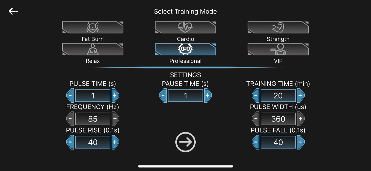
5. Professional
-
Pulse Time: 1 second
-
Pause Time: 1 second
-
Frequency: 85 Hz
-
Pulse Width: 360 µs
-
Pulse Rise: 4.0 seconds (40 × 0.1s)
-
Pulse Fall: 4.0 seconds (40 × 0.1s)
-
Training Time: 20 minutes
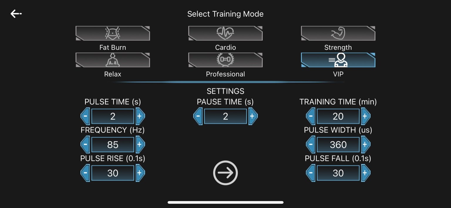
6. VIP
-
Pulse Time: 2 seconds
-
Pause Time: 2 seconds
-
Frequency: 85 Hz
-
Pulse Width: 360 µs
-
Pulse Rise: 3.0 seconds (30 × 0.1s)
-
Pulse Fall: 3.0 seconds (30 × 0.1s)
-
Training Time: 20 minutes
Parameter Adjustment During Workout


Best Chips:
-
STM32F103C8T6 — balanced, affordable, USB, PWM
-
GD32F103VCT6 — STM32 clone, more flash/RAM
Channels Breakdown:
-
Arms
-
Chest
-
Abs
-
Shoulders
-
Upper Back
-
Lower Back
-
Glutes
-
Legs
-
All (Global override)
Best Control Chip (MCU)
Top Choice: STM32F103C8T6
-
Core: ARM Cortex-M3 @ 72 MHz
-
PWM: Multiple timers with advanced PWM (great for EMS)
-
I/O: Enough GPIOs for 10 channels
-
Interfaces: UART, SPI, I2C, USB FS
-
Cost: ~$1.30 in bulk
-
Toolchain: STM32CubeIDE, PlatformIO, Arduino-compatible
Alternative: GD32F103VCT6 (You already have)
-
Very similar to STM32, but lower cost
-
Good for cost-sensitive production
-
Fully compatible with STM32 firmware in most cases
-
No built-in USB (depends on model version), but some support USB FS
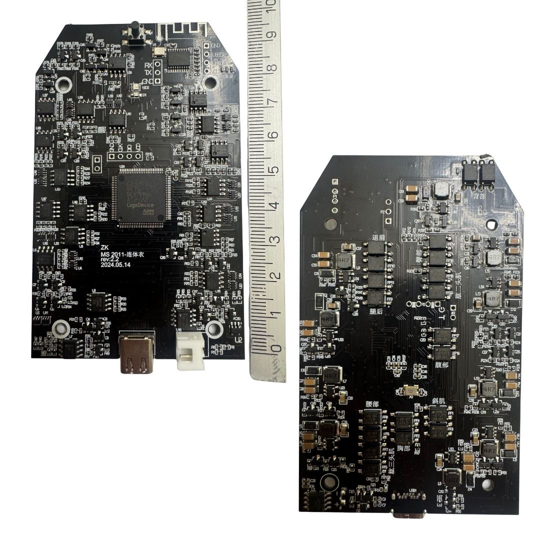
THE PCB Board & Components
Here are images of four PCB boards from existing manufacturers. These are provided for reference only, to illustrate functionality and general requirements—we are looking to develop a new and improved custom design.
We require the complete development package, including:
-
PCB design and assembly
-
Gerber files
-
BOM (Bill of Materials)
-
Firmware
-
Functional prototype with full documentation
-
Support for bulk production, including quarterly and monthly manufacturing planning
Additionally, we expect the engineer to consult us and guide us in selecting the best technical and high-quality components and solutions.
As the customer, we may not have full technical knowledge—we rely on your expertise to explain the purpose of each element and advise us on the most suitable options to achieve the highest performance and reliability.
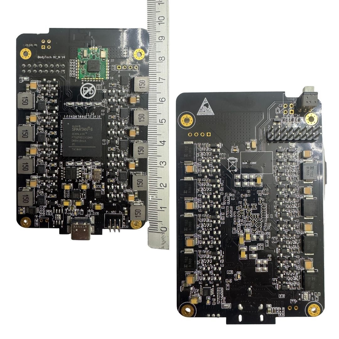
Bodytech EMS Device
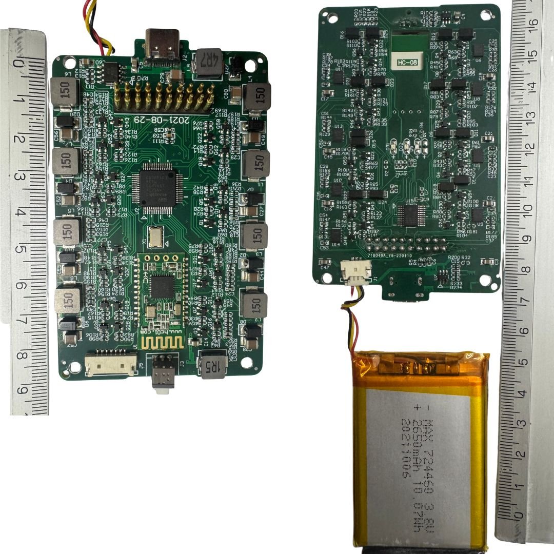
GS EMS DEVICE Gomang
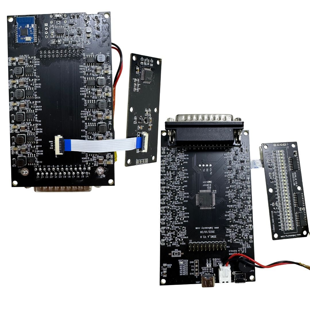
Gugeer EMS Device
MBODY EMS Device
Recommended USB Interface
Top Choice: CH340C / CH340E
-
Very low cost (~$0.30–$0.40)
-
Works via UART to USB bridge
-
Widely used in low-cost devices
-
Easy to integrate into PCB
Alternative: CP2102 / FT232RL
-
More reliable and stable drivers
-
FT232 is more expensive (~$3) but has better signal handling
-
CP2102 is a good mid-range ($1–$2)
Optional with BLE SoC:
If you want to simplify further and avoid a separate BLE chip + MCU:
🔴 All-in-One Option: nRF52840
-
BLE 5.0 + USB + PWM in one chip
-
No need for CH340 or STM32
-
Cost: ~$2.50–$3.00
-
Downside: More complex to program if you’re used to STM32
Pro Combo Setup
| Component | Model | Why |
|---|---|---|
| MCU (Main) | STM32F103C8T6 | 72 MHz, USB FS, good timers |
| BLE Module | nRF52832 (UART/SPI) | BLE 5.0, mobile app control |
| USB to UART | CH340C | Cost-effective and simple |
| Voltage Reg. | AMS1117-3.3 | For BLE & MCU if battery = 3.7V |
Final Recommendation for 10-channel EMS:
| Purpose | Component |
|---|---|
| Main MCU | STM32F103C8T6 |
| USB Connection | CH340C |
| BLE Connectivity | nRF52832 UART module |
System Schematic Overview – STM32F103C8T6 + nRF52832 BLE (9-Channel EMS Controller)
Core Components
MCU: STM32F103C8T6
-
Controls all 9 EMS channels via PWM
-
Communicates via UART with the BLE module
-
Can be programmed via native USB FS or through CH340C USB–UART bridge
BLE Module: nRF52832 (UART interface)
-
Receives training program commands from mobile app (BLE 5.0)
-
Sends intensity, duration, and start/stop control to the STM32
USB Interface: Native USB or CH340C
-
For firmware upload and optional PC app control
-
Connects to STM32 USB D+ / D− pins
Power Supply
-
Battery: 3.7V LiPo rechargeable
-
Voltage Regulation: AMS1117-3.3V drops voltage from 3.7V to stable 3.3V for STM32 and BLE
PWM Channel Outputs
| Channel | Target Muscle Group | Output Type |
|---|---|---|
| PWM0 | Arms | PWM → MOSFET Driver → Electrodes |
| PWM1 | Chest | PWM → Driver → Electrodes |
| PWM2 | Abs | PWM → Driver → Electrodes |
| PWM3 | Shoulders | PWM → Driver → Electrodes |
| PWM4 | Upper Back | PWM → Driver → Electrodes |
| PWM5 | Lower Back | PWM → Driver → Electrodes |
| PWM6 | Glutes | PWM → Driver → Electrodes |
| PWM7 | Legs | PWM → Driver → Electrodes |
| PWM8 | All (Global Override) | Overrides PWM0–PWM7 optionally |
Connections Summary
| From | To | Signal / Voltage |
|---|---|---|
| nRF52832 TX/RX | STM32 UART RX/TX | UART Serial |
| STM32 PWMx Pins | EMS Drivers (x9) | PWM Signal |
| 3.7V LiPo Battery | AMS1117 Regulator | 3.7V input |
| Regulator Output | STM32 + BLE VCC | 3.3V regulated power |
| USB D+ / D− | STM32 USB Pins | USB Full-Speed (FS) |
Here’s a textual version of the full schematic layout for a 9-channel EMS device using GD32F103VCT6, nRF52832 BLE, and USB interface:
System Schematic Overview
Core Components:
-
MCU: GD32F103VCT6
-
Controls all 9 EMS channels via PWM
-
Communicates via UART with BLE module
-
Can be programmed via native USB FS or CH340C
-
-
BLE Module: nRF52832 (UART interface)
-
Receives commands from mobile app (BLE 5.0)
-
Sends training parameters to GD32 MCU
-
-
USB: CH340C or Native USB
-
For firmware upload and potential PC communication
-
Connects directly to GD32 USB pins (D+/D−)
-
-
Power Supply
-
Battery: 3.7V LiPo
-
Regulator: AMS1117-3.3V (drops 3.7V to 3.3V for GD32 & BLE)
-
Channel Outputs:
| Channel | Target Muscle Group | Output Type |
|---|---|---|
| PWM0 | Arms | PWM → MOSFET Driver → Electrodes |
| PWM1 | Chest | PWM → Driver → Electrodes |
| PWM2 | Abs | … |
| PWM3 | Shoulders | … |
| PWM4 | Upper Back | … |
| PWM5 | Lower Back | … |
| PWM6 | Glutes | … |
| PWM7 | Legs | … |
| PWM8 | All (Global Override) | Overrides PWM0–PWM7 optionally |
Connections Summary:
| From | To | Signal/Voltage |
|---|---|---|
| nRF52832 TX/RX | GD32 UART RX/TX | UART Serial |
| GD32 PWMx Pins | EMS Drivers (x9) | PWM Signal |
| LiPo Battery | AMS1117 Regulator | 3.7V → 3.3V |
| Regulator Output | GD32 + BLE VCC | 3.3V |
| USB D+ / D− | GD32 USB Pins | USB FS |
BLUETOOTH DEVICE NAME: iBody V1.0
Please note: We will never use the term EMS in our communication. To maintain a unique identity, we refer to our technology as iCA (Intelligent Cell Activation).
eBOX EMS Device Design
Minimalistic modern aluminuim black like apple iphone 15 pro elegant Black Titanium!
PCB & Enclosure Dimensions:
The maximum PCB size is 10 cm x 6 cm, with a preference for smaller dimensions such as 10 cm x 5 cm or 10 cm x 4 cm, if technically feasible. The external box will be adapted to match the PCB size and should be designed to be as small, compact, and minimalistic as possible.


")

Note: The current sliding rail is provided as a basic example only. We do not want this version. The final rail should match the enclosure box in material and appearance—preferably black titanium, identical in finish, and resistant to scratches. If metal is not feasible, then use high-quality plastic that visually and structurally matches the enclosure box.

Charging Solution Requirements:
We require a USB to USB-C charging solution that does not compromise battery lifespan. Battery health and longevity are a priority. If fast charging negatively impacts the battery, it should be avoided. The focus is on a safe, stable, and battery-friendly charging process.
Project Requirements Overview
This summary outlines all essential components and services required to develop our custom EMS device—from hardware and firmware to app development and production support.
App Development:
We require an app developer to build the companion app for both Android and iOS platforms, as the app will communicate directly with the PCB. If you can handle this part, it would be ideal. If not, we kindly ask for a recommendation of a trusted developer capable of delivering the required solution.
Electrode Suits:
If you are able to manufacture the electrode suits as well, that would be a great advantage. If not, we can source a specialized supplier for this component.
Firmware & Technical Details – Electric Impulse:
We can provide five sample EMS devices from various manufacturers to help analyze the Bluetooth protocol and electric impulse signals using an oscilloscope or any additional tools you may require.
However, before moving forward, we need a quotation for:
-
Prototype development
-
Testing
-
Bulk production of 1,000+ units per month or per quarter, depending on market demand
What We Need – Summary
Below is a complete overview of the components and services required for this project:
-
Custom PCB board design and assembly
-
Mobile App Development – Android & iOS
-
Electrode suits – manufacturing or sourcing
-
Firmware – for intelligent impulse control and Bluetooth communication
-
Gerber files, BOM list, and all manufacturing documentation
-
CE Certification (required) and FDA Certification (optional, for future stages)
We appreciate your expert guidance and look forward to receiving your detailed quotation and project proposal.